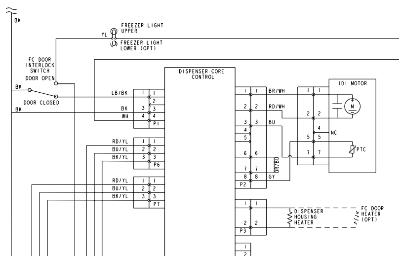
We’ve got an interesting one for you today — take a look at the “IDI Motor” in this schematic:

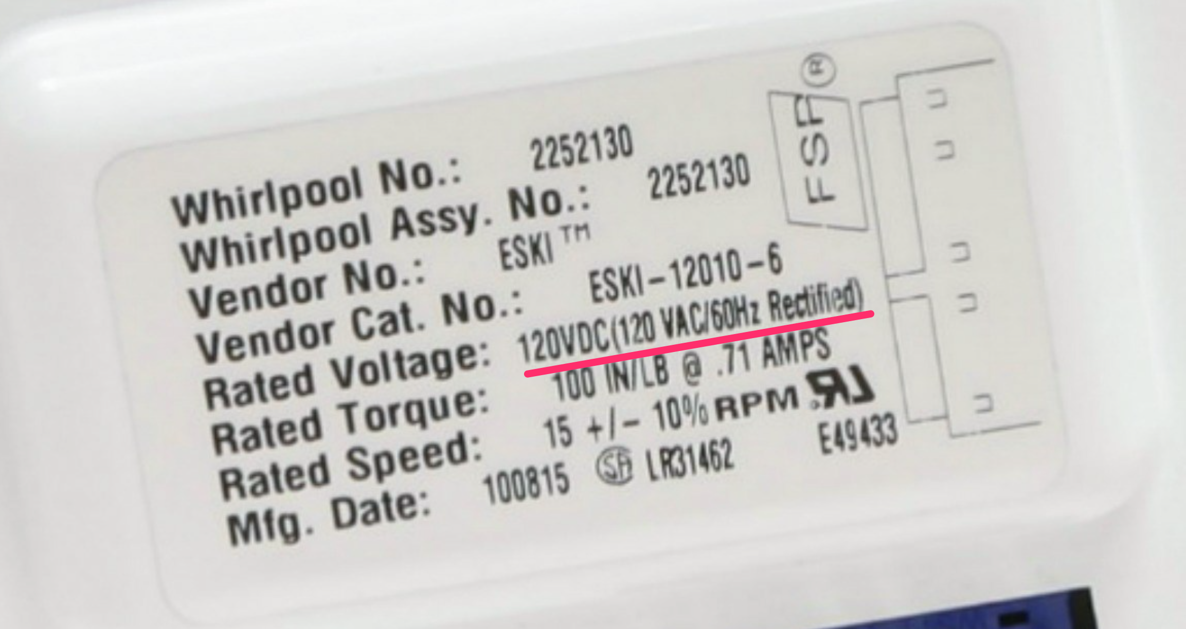
That’s the ice dispenser auger motor in this fridge, and there are a couple interesting things to figure out about it. First, what’s the deal with its power supply? If you look at the label on the motor, you’ll notice that it says:

So that’s a 120 VDC motor. How does that work?
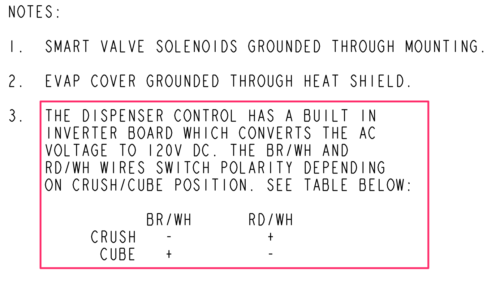
A quick look through the documentation tells us that this motor is designed to run in two different directions, depending on the polarity of the DC power applied to it. Note #3 below shows this:

Did you catch the mistake in Whirlpool’s documentation here? They talk about an inverter converting AC to DC, but that’s actually the opposite of what an inverter does. The label on the motor has it right: you need a rectifier to change AC to DC.
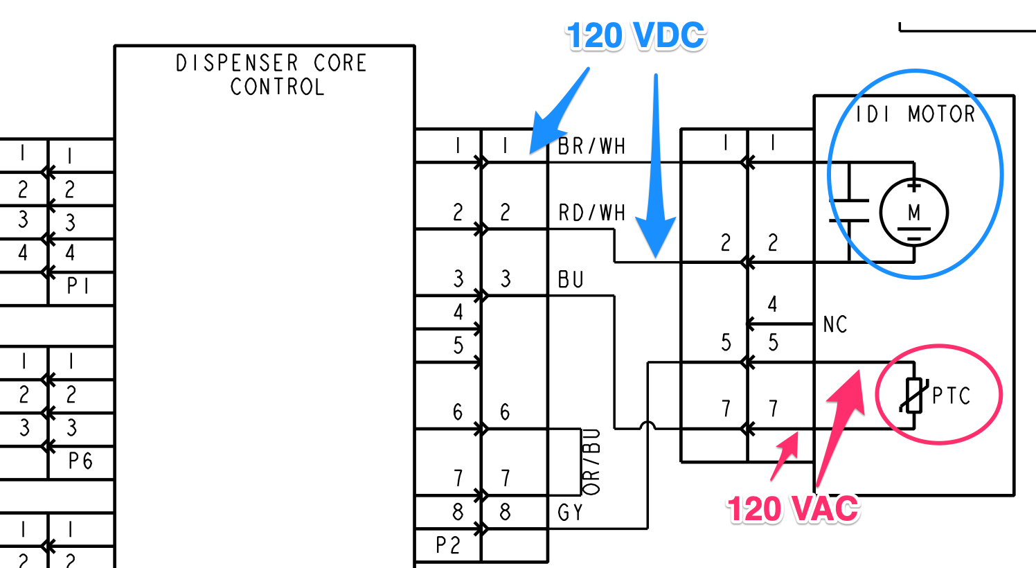
Another question — we can see that there’s a PTC connected to the dispenser control board. We might expect to see something like this as a safety in the motor’s circuit, but it doesn’t appear to be in the motor’s circuit. Rather, it has its own connections to the dispenser control. What’s going on here?
There are no notes giving us the answer on this one, but if we employ some of our own circuit know-how, we can figure out what the purpose of that PTC must be.
Before the board rectifies its 120 VAC supply into 120 VDC for powering the motor, it first sends it through the PTC. Why? As a safety device. If the IDI motor jams during operation, it will cause excessive current that will cause the PTC to open. That cuts off the 120 VAC before it even gets to become 120 VDC, which prevents the jammed motor from receiving power.

Want to learn how to read schematics, understand circuits, and troubleshoot with confidence? Click below to check out our online Core Appliance Repair training course right here at the Master Samurai Tech Academy.