By now, most of us are used to variable speed drive motor systems in appliances. The control board sends a PWM signal to an inverter, which tells the inverter how fast to run the BLDC motor.
While this is the type of inverter that’s been used in appliances for years now, it’s not the only kind of inverter out there. In fact, another type of inverter is starting to crop up in the appliance world, and it may very well become the norm for some applications. It’s called a drop-in inverter, and we’re going to look at what sets it apart from the PWM-controlled inverters we’re used to.
First, let’s take a look at a standard PWM-controlled inverter schematic — this happens to be for a refrigerator.
In this configuration, the inverter takes four inputs: a hardwired line and neutral, and then two connections to the main control board. The red connection on this schematic is the PWM signal line — that carries the DC square wave that the control board uses to tell the inverter what to do. Then the white wire would be for DC ground.
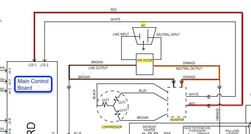
Now let’s take a look at the schematic for a drop-in inverter — also in a refrigerator.
It actually looks almost identical to the PWM-controlled inverter, but with a crucial difference: there’s only one connection from the control board to the inverter. And that connection isn’t carrying a DC signal — instead, it carries a simple 120 VAC.
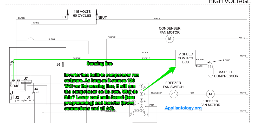
This is why these inverters are called “drop-ins”. Instead of the main control board needing to have special programming so that it can send instructions to an inverter, it just needs to send 120 VAC when it wants the compressor to run, and take away the 120 VAC when it wants it to stop. The inverter has all the programming for running the motor by itself.
Right about now, the inquiring minds among you may be asking yourselves, “How is the inverter supposed to vary the speed of the compressor motor in response to sensor data? Isn’t that the whole point of a variable speed compressor?”
Hey, good questions! The answer is that the manufacturer of this refrigerator isn’t interested in granular control over the speed of the compressor. They’re fine with it just running at full speed during operation, with no variance in response to thermistor readings or any other inputs. That’s probably because they noticed that, in their models with PWM-controlled inverters, the compressor was almost always being run at maximum capacity. So the variable speed functionality wasn’t used much.
But that begs another question: why even bother using an inverter and BLDC motor setup in that case? Why not just use an old-fashioned split-phase compressor?
This is because, even if the drop-in inverter runs the compressor at full bore during operation, it still has programming that lets it ramp up and ramp down the compressor when starting and stopping it. That takes a lot of strain off the motor, helping improve its lifespan and efficiency. So it’s just a strict improvement over a split-phase compressor.
One more important thing to point out: we’ve just been looking at one possible implementation of these drop-in inverters. Some of these inverters have the capacity to take both a 120 VAC drop-in signal and also a PWM speed signal. As an example of that, click here to see a product manual for an Embraco CF05D drop-in inverter that has both functionalities (you must be a premium tech member of Appliantology to download it).
Hope you found this quick dive into inverter technology informative! If you’d like to learn more about the technologies that are fundamental to all appliances, click here check out our Core Appliance Repair Training course right here at the Master Samurai Tech Academy.