Take a look at the circuit for this electric cooktop element. Notice anything odd about it?
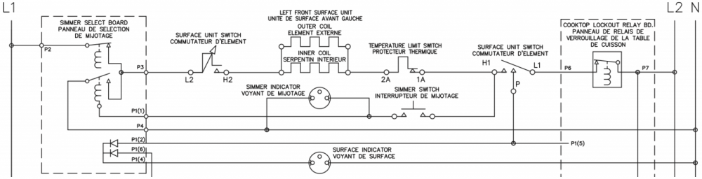
Looks pretty straightforward, right? Well, it certainly is straightforward when the simmer switch isn’t closed. Here’s what the circuit looks like when it’s not running on simmer.
L1 goes through the simmer select board and a temperature-controlled switch, and L2 goes through the relay board and a couple other switches. Standard stuff for one of these elements.
But what’s going on with those coils on the simmer select board? There’s a double pole switch there, with one of the poles shown normally closed (the one that has L1 going through it to the elements) and the other normally open. What’s the deal with these switches, and what do they have to do with the simmer function?
Furthermore, what’s going on with those coils shown by each switch? Normally those indicate electromechanical relays, but the way the schematic is drawn, it looks like only one end of one of those coils is connected to the power supply. What gives?
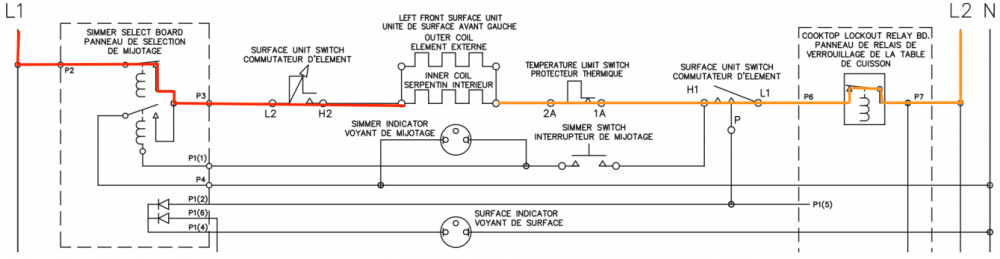
This is one of those situations where you have to work around the vagueness of the schematic using your technical know-how. You know how things have to work — for example, that a load needs to have a valid voltage supply and return in order to operate. Regardless of how strangely the engineers have drawn up those relay coils, we know that they have to be connected to the power supply somehow, even if it’s not explicitly shown. It’s just the only way in which this circuit can operate.
Once we’ve made that deduction, we can start tracing out what happens when the simmer switch is closed. L2 runs through the simmer switch and powers the relay coils, which in turn closes the lower of the two switches and opens the other one. This results in the following circuit configuration:
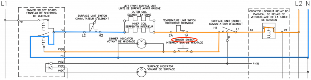
And now you see why this is the simmer function — all this fancy switching around is just reducing the power supply to the elements from 240 VAC to 120, which will reduce the heat output. That would have been a lot clearer if the schematic had been drawn better, but hey, figuring out stuff like this is part of the job.
Want to learn how to read schematics and apply that knowledge to real-world troubleshooting? Click below to check out the Core appliance repair training course right here at the Master Samurai Tech Academy.