Dryer Schematic Quiz – Click for Larger View (opens in a new window)
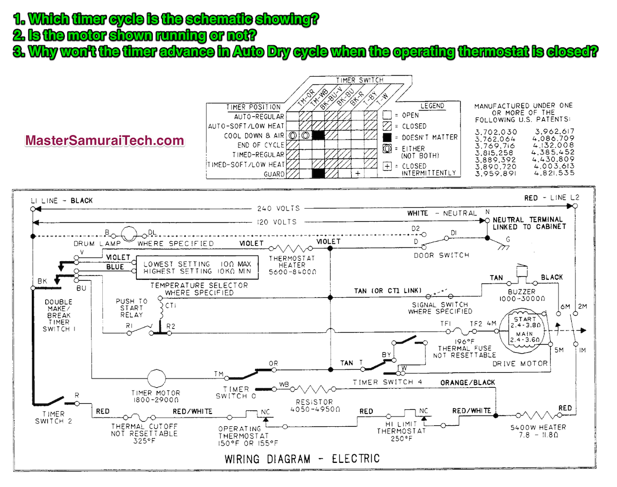
1. Which timer cycle is the schematic showing?
Looking at the timing chart, we see that the cycles on this dryer fall into two main groups: auto and timed. The big distinction between the two is timer contacts TM-OR (timed dry cycles) and TM-WB (auto dry cycles). Since the schematic shows that the TM-OR contacts are made, then we know we’re in a timed dry cycle. Checking the state of the other contacts listed in the timing, we see that the schematic shows them all as open. Therefore, we know that this dryer schematic is showing the dryer at the End-of-Cycle. Which also helps answer the next question…
2. Is the motor shown running or not?
We know from the forgoing analysis that the dryer is shown at end-of-cycle, so the motor is not running. But you can also tell by looking at the centrifugal switch contacts on the motor. They are shown in the retracted state meaning the motor is stopped.
3. Why won’t the timer advance in Auto Dry cycle when the operating thermostat is closed?
In Auto Dry, the timer chart shows timer contacts TM-WB are made. With this in mind, trace L1 to the timer motor. L1 comes through timer contacts BK-BU to one side of the timer. L1 also comes through timer contacts BK-R, through the thermal cutoff, operating thermostat, and high limit to one side of the heater. But it also branches off through the resistor and timer contacts TM-WB to the other side of the timer. Since both sides of the timer have L1, the voltage difference across the timer is zero and the timer motor does not run.
Still confused? I explain and demystify circuits, reading schematics, troubleshooting with schematics, motors, and all the other basic skills that every appliance tech should have in our Core Appliance Repair Training course. Complete our free Sample course and get a discount off your tuition.