Every other week, Master Samurai Tech/Appliantology.org holds a Live Dojo workshop where techs gather to workshop various technical and business problems. These workshops are help online via Zoom at 10 AM ET and last for about an hour, sometimes a little more. This post is a recap of the Live Dojo we had on Saturday, February 10.
The two main topics we covered this time were a mystifying problem with the cooktop lights on a microwave and an in-depth discussion of how to read an old-school washer’s timer chart. This included points like:
- How lights can be dimmed by including a diode in their circuit
- Possible causes for a light that burns out as soon as it’s installed
- Troubleshooting strategies for loads that never stop running
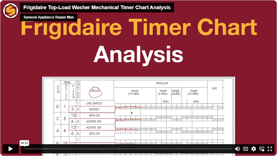
- How to interpret the different cam and contact numbers on a mechanical timer chart
- Identifying which lines on the schematic represent internal timer circuitry
- Analyzing circuits using both the timer chart and schematic together
Keep scrolling for a summary of the conversations. Here’s a recording of the first part of the Live Dojo, covering the cooktop lights – viewable only by premium members of Appliantology.
Not a premium member? You can become one today for free by enrolling in any technical course right here at Master Samurai Tech.

How a Cooktop Light with a Diode in its Circuit Works
Sam presented a cooktop circuit and explained the functionality of the relays and diode. The light runs at normal brightness when one relay is closed, but when the other relay closes that includes a diode in the circuit, it cuts off half of the power supply’s sine wave, either positive or negative, depending on its bias. The group concluded that this results in the lights dimming, as the current is halved when the Night mode relay is closed.
Potential Cooktop Light Problems Discussed
The group discussed this cooktop light in the context of an Appliantology topic. The problem was that one light kept burning out immediately after installation, while another wouldn’t shut off. They considered several possible causes, including a short or a faulty bulb, and discussed how to troubleshoot the problem. They discussed the possibility of a stuck relay in the light circuit. The team agreed that if the relay was stuck, it could cause the light to stay on. They suggested testing for voltage across the contacts to identify which relay was stuck.
Here’s a recording of the second part of the Live Dojo, covering the timer charts – viewable only by premium members of Appliantology.
Not a premium member? You can become one today for free by enrolling in any technical course right here at Master Samurai Tech.
Schematics, Timer Charts, and Troubleshooting
Scott led a discussion about schematics and mechanical timers, stressing the importance of using the timer chart to understand the circuits. The group examined an example schematic of a washer, identifying key components. Scott then introduced the timer chart, using it to discuss a problem scenario involving a malfunctioning water inlet valve. Scott emphasized the troubleshooting process, highlighting the importance of consulting technical documents and planning a strategy before taking action.
Power Supply Control and Timer Switch Schematic Discussion
Scott continued the discussion of this problem scenario by analyzing the power supply of various loads in a machine, using the timer chart and schematic together to understand how each load got power. He focused on the wash cycle, explaining which switches are closed during this phase, and identified a mislabelled contact in the timer chart, showing how you can spot such mistakes and account for them.
Timer Contacts vs. Cam Numbers
Scott and Sam explained the relationship between the cam numbers and timer contact numbers given on the timer chart, noting which numbers on the schematic are referring to cams and which are referring to contacts. The group also discussed the importance of marking up schematics and using tools like iPads to better visualize and understand the connections. Scott showed how to trace the circuits on the schematic and how to tell which contacts are being connected by a given switch. Sam added that when a timer switch is closed, two timer contacts become electrically equivalent points.